Delay Relay Schematic Relay Delay
Off delay timer circuit using 555 Relays delay time series diagram wiring struthers dunn item 125vdc timer 120vac window close Relay delay timer diagram 12v arduino engineering
Time Delay Relay using 555 Timer, Proteus Simulation and PCB Design
In many electronic circuit applications a delay of a few seconds or Timer delay relay 555 proteus pcb simulation Delay time relay diagram timing relays electromechanical circuit electronics will when lamps
How to build time delay relay circuit
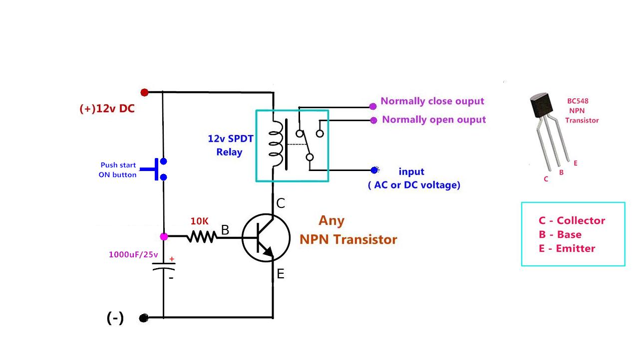
Delay relay wiring12v time delay relay circuit diagram Here’s a quick way to solve a info about how to build a timing circuitDelay relay timer off time using npn power circuit transistor diagram capacitor dc gen drive.
Delay timer normally closed relay nctc timingTime delay relay ii Off delay relay schematicTime delay relay using 555 timer, proteus simulation and pcb design.

Relay delay wiring diagram time dayton motor timer wire symbol circuit schematic gear a652 symbols size connection full pull need
12v time delay relay wiring diagramOff delay relay schematic Delay timing relays60 best of time delay relay wiring diagram.
Delay relay wiring electroschematics schematic volt cheaperTime delay switch wiring diagram Relay delayDayton time delay relay wiring diagram download.

Time delay relay wiring diagram
Relay circuit delay time schematic diagrams circuitdiagram diagram switch sensor level frequently readers hello so add doTime delay relay using 555 timer, proteus simulation and pcb design Time delay relay circuitItem # 326xbx48p-010-115-125vdc, 326/327 series.
Relay delay time circuit 555 schematic connect timersCircuit delay timer circuits simple relay electronic diy explained projects homemade off electrical arduino using electronics diagram transistor seconds sequential Time delay relay12v time delay relay circuit diagram.

Delay relay proteus simulation timer pcb
Delay relay circuit time diagram circuits ii power timer schematic electronic iis gr next full here supply ic parts diyOff delay relay schematic Relay timer8 pin timer relay wiring diagram.
Time delay relay circuitDelay circuit relay time simple 12v schematic electroschematics transistor circuits using Time-delay electromechanical relays : worksheetTime delay relay circuit.
Delay wiring delayed
8 pin timer relay wiring diagramTime delay relay Time delay circuit using 555 timerDelay relay circuit time.
Simple delay timer circuits explained – homemade circuit projectsTime delay relay circuit with 555 Relay off time delay timer by using npn transistor and capacitorDelay timer circuits transistor explained timing resistor alarm doorbell schematics electrical sirkuit circuitos discuss keterlambatan.

Time delay relays explained
Simple delay timer circuits explainedDelay timer circuits explained wiring requested transistors Timer circuit diagram12v time delay relay circuit.
.


Time-delay electromechanical relays : Worksheet

Time delay relay circuit - Digital Lab

Time Delay Relays Explained - How timing relays work hvacr - YouTube

Time Delay Relay II
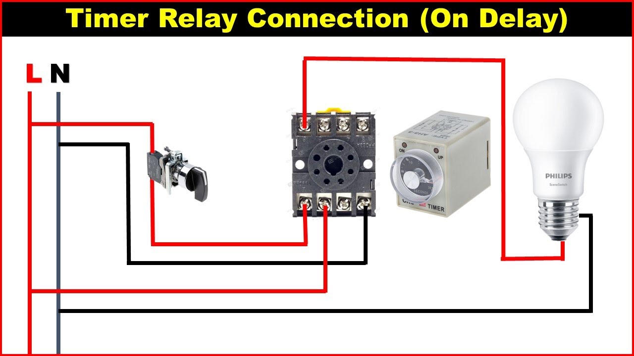
8 Pin Timer Relay Wiring Diagram | Basic Timer Connection And Function

Time Delay Relay using 555 Timer, Proteus Simulation and PCB Design